![Throw Away? Fixed! [EP 1] Portable USB/FM/Bluetooth Radio](Modification%20of%20the%20ZD-915%20desoldering%20iron%20to%20work%20with%20the%20SOLOMON%20SL-2%20gun_files/9473154400_1745769601_thumb.jpg)


Here I will show my modification of the ZD-915 desoldering iron to work with the SOLOMON SL-2 gun.
I made the changes provisionally some time ago, but I am satisfied, so it was time to make it "ready". The photos are mostly from the prototype version.
The ZD-915 does not "enjoy" a good reputation and indeed, working with it was quite frustrating. It took a very long time to heat up, and when it did heat up, putting the tip to the joint caused it to cool down quickly and often stick to the solder. For this reason, I had the temperature set to maximum most of the time. Additionally, the roar of the fan from the first moment after switching it on irritated me a lot, because the volume of its operation can hardly be called anything other than a "roar".
The first modification was to completely turn off the fan, but this is only a cosmetic change. The device works occasionally, not in continuous mode, so even without the fan it does not heat up too much.
Then I noticed that the gun says "24 V", and the actual supply voltage of the heater is about 18 V. So I modified the power supply to provide the aforementioned 24 V.
The modification consists of replacing the R8 resistor from 24 kΩ to 18 kΩ on the power supply board. This requires removing it and removing the casing. The pump motor is twelve-volt, so the original power supply is provided by a black box on the back wall. There are simply series resistors there. Without thinking twice, I changed them to the ones I had on hand. This is not an elegant solution, so a 24/12 V converter purchased for pennies on a Chinese website will go inside. The voltage from the power supply also goes to the control board, where it is fed to the processor via a resistor divider. I don't know what the purpose of this is, whether the processor measures something or checks the presence of voltage, but it is worth changing the resistor in the divider so as not to raise the voltage on the processor pin too much. Resistors R6 and R10 in the diagram below. The markings match those on the controller board. The work culture improved, the gun heated up quickly and maintained the set temperature better. After some time, however, the heater burned out - it was probably not without reason that it was powered by a reduced voltage. I did not want to continue investing in equipment that did not work properly anyway, and an unused SOLOMON SL-2 gun was waiting in the drawer for its opportunity. I decided to connect it to the station as freely as possible and try how such a solution would work.


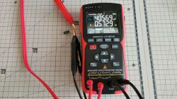
First of all, SOLOMON has a different pinout in the plug, so something needs to be changed. Since the Solomon cable was stiffer than the one I used (maybe from age and lying rolled up for a long time), I simply took the cable out of the ZD-915 gun and installed it in the SL-2, taking care to connect it as in the ZD-915. The SL-2 heater has a different thermocouple than the one in the ZD-915, but there is nothing you can do about it on the gun side. I had to go back to the station and dig inside again. I started by connecting a regulated voltage source instead of a thermocouple and observing the display readings depending on the signal I set. The potentiometer on the control board remained in the position it was in at the beginning. Then I carried out several tests for its other positions. For the minimum position, the displayed temperature did not change, and I added the measurements from the middle and maximum positions to the graph. The blue line is the existing position, the light blue is the middle position, and the green is the maximum (far right). I heated the Solomon heater with an external heat source, and noted the output voltage of the thermocouple. These are the dark blue points on the graph. For comparison, I also plotted the characteristics of several popular thermocouples. As you can see, Solomon is a K thermocouple, and ZD-915 is who knows what. It's like E, but with a large offset. To make the conversion, I quickly assembled an amplifier with adjustable gain and offset on the popular TL081, of which I also had a few spare. To power it, I used an isolated converter with a symmetrical output, but it is possible that the opamp could be powered asymmetrically, because we do not expect negative voltages at either the input or output. I did not test it. RV1 is used to adjust the offset, and RV2 is used to adjust the gain. Following the diagram, a board was quickly created that can be easily made at home. There is plenty of space, no need to bother with miniaturization, I had a through-hole TL081, as well as quite large potentiometers. I generally don't like THT, because it requires drilling and is quite clumsy, so the passive elements are SMD. I had a working system in one evening without any problems. The 5V power supply was easy to get from one of the unoccupied connectors on the control board - just solder the goldpins or cables directly. I chose soldering, but maybe this will change in the final version.


I disconnected the thermocouple wires from the socket on the ZD-915 housing from the control board and routed them to the input of my converter, while I connected the converter output to the controller. This also requires soldering, because originally these wires, probably the only ones, are not on the connector but soldered. I inserted the thermocouple of an external thermometer into the tip of the tip, set the minimum and maximum temperature on the station, and by manipulating the RV1 and RV2 potentiometers I made the temperature set on the station match the temperature measured on the tip. For convenience, I marked them on the board: "O" for "offset" and "G" for "gain". The original potentiometer on the control board in the middle position. I have been using this monster for some time now and it works very well. You just have to get used to the fact that the trigger in the SL-2 works the other way around, i.e. instead of pressing it, you have to lift it by the protruding tongue.

Cool? DIY Ranking


